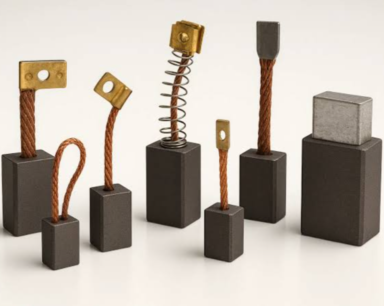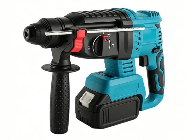
How do I know what size carbon brush I need?
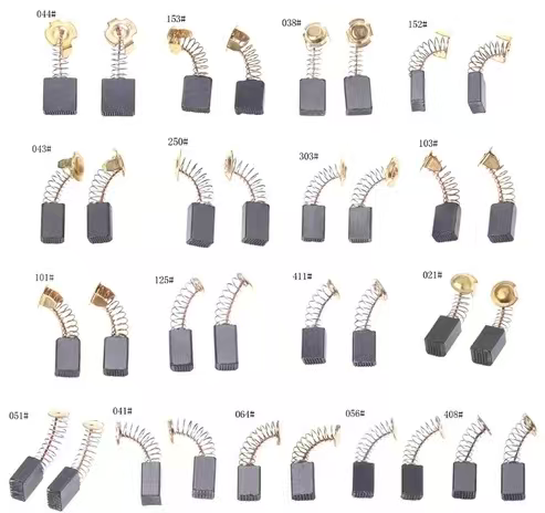
How do I know what size carbon brush I need?
How do I know what size carbon brush I need?Users can accurately determine the correct carbon brush size for any motor device through five reliable and systematic methods including original factory label tracing, precise dimensional measurement of old brushes, installation structure parameter matching, working condition reverse derivation and auxiliary detail verification, which together eliminate size mismatch errors and ensure perfect fit and stable operation of new replacement carbon brushes.
Tracing Original Factory Markings for Accurate Parameter Reference
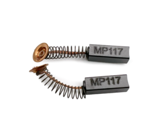
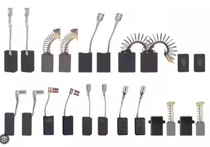
Checking the surface markings of the original old carbon brush is the most straightforward and efficient way to confirm matching specifications without complicated measurement and calculation. Most standard formal carbon brush products are printed or engraved with complete parameter information on their side surfaces during factory production, covering precise overall dimensions, official model numbers and specialized material codes. These marking parameters are customized according to the matched motor model, with extremely high accuracy and pertinence.
In daily replacement maintenance, users only need to remove the worn carbon brush and carefully observe its smooth side shell to read the complete size data and model coding. The parameters marked on the brush body are the factory-standard specifications applicable to the equipment, which can be directly used as the selection basis for new carbon brushes. This method completely avoids manual measurement errors and is suitable for almost all civilian tools and industrial motor equipment with complete markings.
Even if the carbon brush is severely worn and shortened after long-term operation, the side marking area will not be worn and damaged, so the parameter information can still be read clearly. It is the most convenient and error-free primary selection method for ordinary maintenance and replacement scenarios.
Querying the original official equipment manual provides the most authoritative and credible size reference for carbon brush selection, serving as the ultimate standard for verifying brush specifications. Every formal motor and electrical equipment will be equipped with a complete factory maintenance and instruction manual, which records all matching accessory parameters and maintenance specifications in detail.
The dedicated carbon brush parameter column in the manual clearly indicates the standard matching size, official model and applicable material type of the carbon brush required for the motor. Different from the limited information on the carbon brush surface, the official manual also marks the parameter tolerance range and applicable working condition standards, helping users select accessories that fully comply with factory design specifications.
This tracing method is especially suitable for scenarios where the old carbon brush markings are blurred, worn out or unrecognizable. By strictly following the official manual parameters, users can completely avoid problems such as size mismatch, poor contact and installation jamming caused by incorrect selection, and ensure the motor operates in the original factory designed state after replacement.
Precision Dimensional Measurement of Original Worn Carbon Brushes
When original markings are unavailable, precise manual measurement of the old carbon brush becomes the core method to confirm matching specifications, and three-dimensional dimension detection with a vernier caliper can obtain accurate reference data. The key measurement objects include three core dimensions of the carbon brush working body: length, width and height, which jointly determine whether the carbon brush can be installed and used normally.
In the whole measurement process, strict error control is required, and the dimensional deviation must be controlled within ±0.5 millimeters. Excessive dimensional errors will cause obvious installation problems. If the new carbon brush is slightly oversized, it will be stuck inside the brush holder and cannot slide flexibly; if it is slightly undersized, it will shake violently during operation, resulting in unstable contact, abnormal sparking and accelerated wear. Reasonable error tolerance ensures the fitting flexibility and operational stability of the new carbon brush.
Multiple repeated measurements should be taken for each dimension during detection to exclude accidental measurement deviations, and the average value should be taken as the final selection reference. Standardized measurement operations can effectively restore the original factory size specifications of the carbon brush and provide accurate data support for subsequent accessory selection.
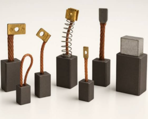
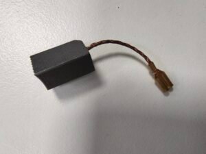
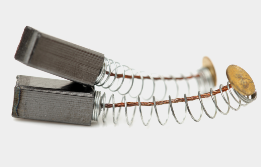
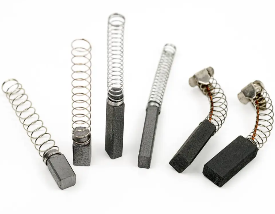
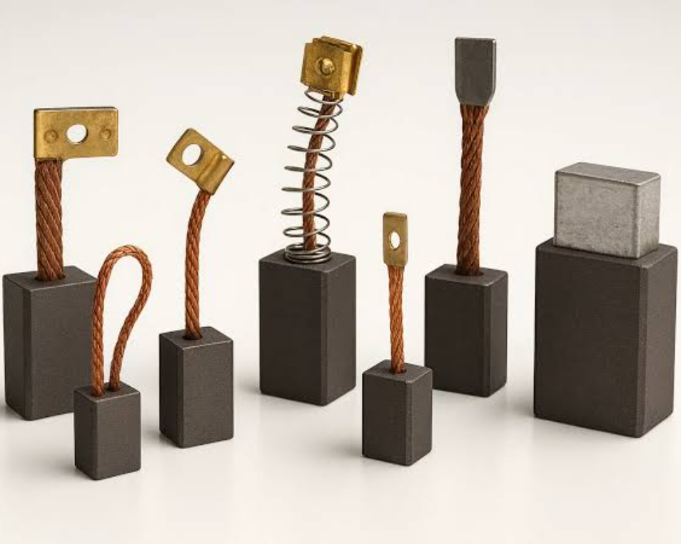
It is crucial to standardize the measurement range and only measure the effective working part of the carbon brush to avoid invalid dimensional data. The complete carbon brush structure includes not only the carbon working body that contacts the commutator, but also auxiliary structures such as tail lead wires and fixed buckles, which are not part of the core size parameters and cannot be included in the measurement range.
The tail lead wire is only a conductive connecting component with no effect on installation fitting and sliding friction, while the fixed buckle is a customized limit structure for individual equipment. Measuring these auxiliary parts will lead to overestimated size parameters and wrong selection of new carbon brushes that cannot be installed normally.
Maintenance personnel need to distinguish the functional areas of the carbon brush clearly, focus on measuring the regular carbon main body that slides inside the brush holder and contacts the commutator, and ensure that the measured data completely matches the effective installation size, so as to guarantee the accuracy of subsequent selection work.
Matching Carbon Brush Specifications with Installation Structural Parameters
Matching the inner diameter parameters of the brush holder is the key to ensuring flexible sliding and stable installation of the new carbon brush. The length and width dimensions of the carbon brush must strictly fit the inner cavity size of the motor brush box, also known as the brush holder, which directly determines the sliding state of the brush during operation.
The industry has a standardized gap standard between carbon brush and brush holder, with the reasonable clearance controlled between 0.1 millimeters and 0.3 millimeters. Within this gap range, the carbon brush can slide up and down freely with wear consumption under the pressure of the spring without jamming and stagnation. At the same time, the gap is small enough to avoid excessive shaking and offset of the carbon brush during high-speed operation.
If the matching gap is too small, the carbon brush will be stuck in the brush holder as it wears, unable to make up for the wear distance in time, resulting in poor contact and power failure; if the gap is too large, the carbon brush will swing left and right during operation, causing unilateral eccentric wear, commutation sparking and abnormal noise. Accurate inner diameter matching ensures long-term stable sliding contact of the carbon brush.
Confirming the effective installation stroke of the carbon brush guarantees continuous and reliable contact throughout the entire service cycle. The total length of the selected carbon brush needs to meet the stroke demand of the spring compression structure, ensuring that the spring can always press the carbon brush firmly and evenly on the commutator surface during the whole wear process.
If the carbon brush is too short in overall length, after a certain degree of wear, the spring will reach the limit compression stroke and cannot continue to push the carbon brush to fit the commutator. This will lead to separation of the contact interface, intermittent current interruption, motor stalling and other faults, even if the carbon brush still has residual wear allowance.
Reasonable overall length configuration ensures that the carbon brush can complete the full wear cycle under the stable pressure of the spring, avoiding early failure caused by insufficient stroke, and maximizing the service life of the carbon brush while ensuring motor operation stability.
Deriving Carbon Brush Size Based on Actual Working Conditions
Selecting the carbon brush cross-section according to the equipment rated load current is an important basis for scientific specification matching, which can effectively avoid overheating and ablation faults under high-current operation. The cross-sectional area of the carbon brush directly determines its current carrying capacity, and there is a fixed matching relationship between current density and cross-section specification in industrial design.
For conventional low-current small equipment, small-section carbon brushes can meet the operation demand, while for equipment with a working current of 200A or above, large-section carbon brushes must be prioritized, such as the mainstream 25×32mm specification. Large cross-sectional area can disperse current density, reduce contact heat generation, and avoid local high temperature and rapid wear caused by excessive current load on a single contact area.
Selecting carbon brush size based on working current is a core rule for industrial motor matching, which can effectively improve the overload resistance of the equipment, reduce thermal wear loss under high-load conditions, and ensure the safe and stable operation of high-power electrical equipment for a long time.
Quickly locking the size range by referring to conventional general specifications of equipment types is an efficient auxiliary selection method. Different types of brushed motors have formed fixed universal standard carbon brush sizes after long-term industrial iteration, which can help users quickly narrow down the selection range and improve selection efficiency.
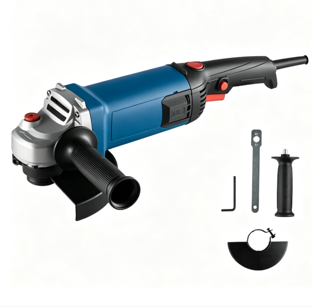
Small civilian power tools represented by electric drills and angle grinders generally adopt small-size carbon brushes with specifications of 6×6×20mm, which are adapted to low-power, high-speed operating characteristics. Conventional industrial medium and large motors have larger matching sizes, with mainstream common specifications including 20×32×50mm and 25.4×38.1×102mm, which are designed for high-load and long-term continuous operation scenarios.
Users can first classify the equipment type according to the motor application scenario, lock the universal size range of the corresponding category, and then combine measurement data and original parameters for precise confirmation. This method greatly reduces the difficulty of blind selection and improves the accuracy and efficiency of carbon brush matching.
Auxiliary Verification of Detailed Matching Parameters
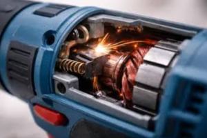
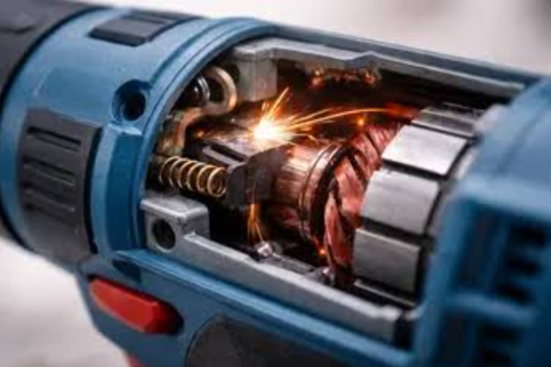
Matching the contact radian of the carbon brush arc surface and the commutator surface is a key detail to ensure sufficient contact area and stable operation. The working surface of qualified carbon brushes is designed with a fixed arc structure, which is completely matched with the outer circular radian of the motor commutator, aiming to achieve full-surface fitting contact.
If the arc radian of the new carbon brush does not match the commutator, the contact state will be point contact or line contact instead of full-surface contact. The insufficient contact area will lead to increased local current density, frequent commutation sparking, and concentrated frictional wear. This will not only affect the motor power output, but also cause rapid ablation failure of the carbon brush in a short time.
Before installation and use, users need to carefully check the fitting degree of the arc surface. For carbon brushes with slightly mismatched radians, fine grinding and running-in can be carried out appropriately to ensure maximum contact area and eliminate hidden dangers of abnormal operation.
Verifying the tail lead specification and terminal position ensures zero-modification direct installation and wiring adaptation. The tail lead wire and fixed terminal of the carbon brush are key connecting structures for current conduction, and their specifications and installation positions are customized for the original motor wiring structure.
When selecting new carbon brushes, users need to check whether the thickness of the lead wire, the length of the wire body and the installation position of the conductive terminal are consistent with the original old parts. Mismatched terminal positions will lead to inability to fix and wire normally, while inappropriate lead wire specifications will cause wiring tension, virtual connection and even wire breakage faults during equipment operation.
Completing the verification of wiring details can avoid secondary modification and processing during installation, ensure that the new carbon brush can be directly installed and used, maintain the original circuit stability of the motor, and avoid circuit faults caused by improper wiring matching.
Q&A Session
Q1: What is the most accurate way to confirm carbon brush size?
The most accurate and authoritative method is to refer to the original factory markings on the old carbon brush and the official equipment manual, which provide factory-standard parameters without measurement errors. When markings are missing, precise vernier caliper measurement of the carbon brush’s effective working dimensions, combined with brush holder gap matching, can ensure accurate size selection.
Q2: What gap standard should be followed for carbon brush and brush holder matching?
The standard fitting gap between a qualified carbon brush and brush holder is controlled at 0.1mm to 0.3mm. This gap ensures the carbon brush slides flexibly without jamming or excessive shaking, maintaining stable contact pressure and fitting state during long-term motor operation.
Q3: How does working current affect carbon brush size selection?
The operating current determines the required carbon brush cross-sectional area. High-current equipment above 200A requires large-section carbon brushes to disperse current density and avoid overheating and accelerated wear. Small cross-section brushes are sufficient for low-power and low-current civilian equipment to meet basic conduction demands.
Q4: What auxiliary details need to be checked before finalizing carbon brush selection?
It is necessary to verify whether the carbon brush arc surface radian matches the commutator to ensure sufficient contact area, and check whether the tail lead specification and terminal position are consistent with the original structure. These details prevent poor contact, sparking and wiring adaptation problems after installation.
Summary
In short, the accurate selection of carbon brush size relies on the comprehensive verification of original factory parameters, manual measurement, structural matching, working condition adaptation and detail inspection. Tracing the markings on old carbon brushes and official equipment manuals provides the most authoritative and direct size reference basis. Standardized three-dimensional measurement of the effective working part of old brushes ensures accurate data within a reasonable error range. Strict matching with brush holder inner diameter gaps and installation strokes guarantees flexible sliding and full-cycle stable contact of new carbon brushes. Selecting cross-section specifications and conventional sizes according to equipment current load and type realizes scientific adaptation to working conditions. Auxiliary verification of contact radian and wiring structure details eliminates hidden dangers of mismatched accessories. Combining these multiple selection and verification methods can completely avoid carbon brush size mismatch faults, ensure perfect fitting installation, and maintain the long-term stable and efficient operation of brushed motors.
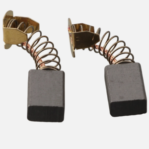
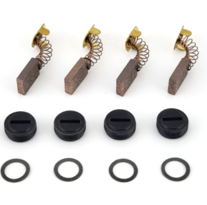
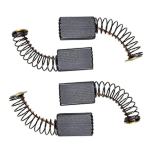
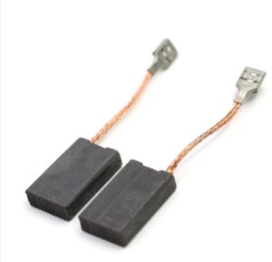
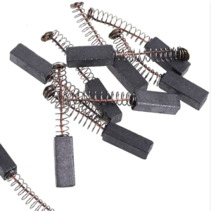
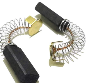
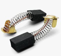
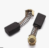
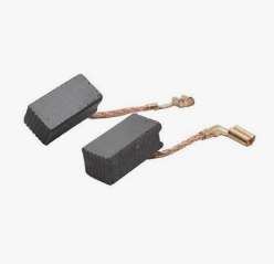
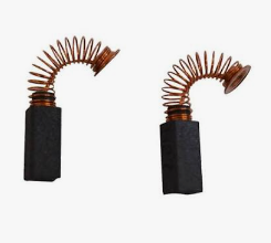
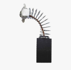
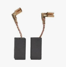
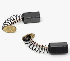
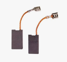
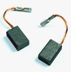
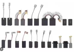
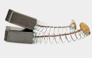
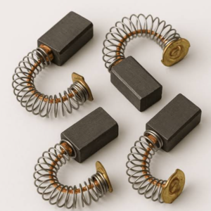
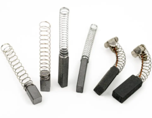
Carbon Brush for Sale:
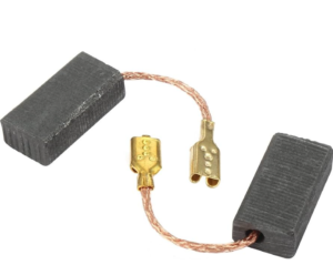
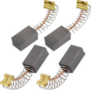
Post about Carbon Brush:
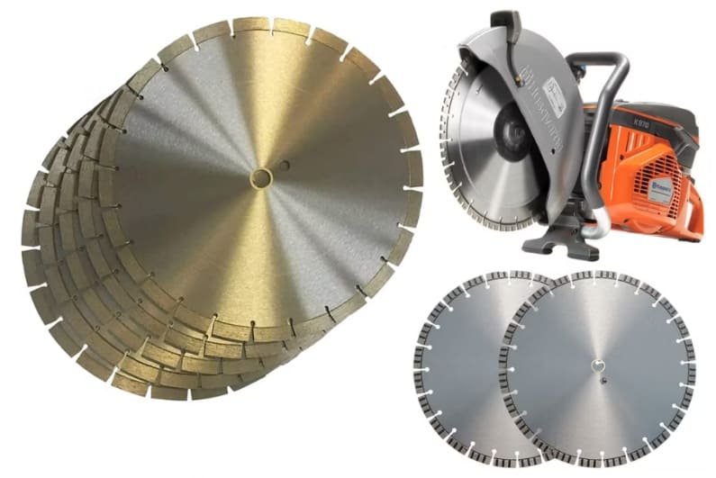
Diamond Blade

Welcome to call us
Contact Us to get quotation
Working Time: 8:00~17:00 Monday to Friday.
Applications:

Factory:
FAQ
Welcome to call us
Contact Us to get quotation
Working Time: 8:00~17:00 Monday to Friday.
Blender Blade:
Chisel Bit:
Cutting Wheel:
Diamond Core Drill Bit:
Flap Disc:
Angle Grinder:
Industrial fan:
Demolition Hammer:
Blogs:
You May also Interest in other topics:
1000 mesh calcium carbonate grinding mill
LMCK Premade bag packing machine